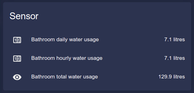
I really started wondering what was using all the extra water in my new house after I got my first water bill. Work and other stuff kept me busy so I forgot it for a while. Finally at one point I realized my toilet flushes it’s tank empty every time, even if the small flush button is used. I took the mechanism apart and fixed it. Obviously the previous dude did not know what they were doing.
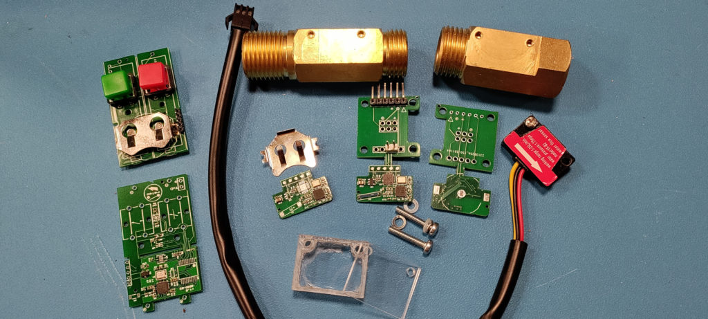
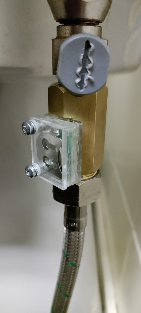
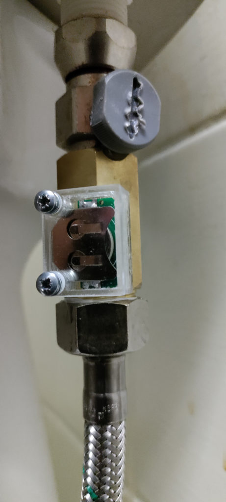
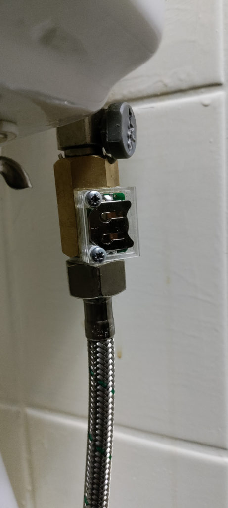
This got me thinking. Is there any equipment available, to the consumer, to be able to measure water usage of individual devices/locations in your apartment? I could not find any, only sensors and stuff like that. So finally I ended up finding these cheap seeedstudio water flow sensors. They seemed to be robust, after all they are made of brass, and they use hall effect so they are not likely to leak when installed correctly.
I ordered couple of these sensors. They worked fine. I got a simple proof-of-concept version working fast by using a FTDI FT232 connected to my laptop as GPIO to read the hall sensor output that was installed on these as default. But it was not hard to find out that the default hall sensor was not gonna cut it, it drew way too much power. Somewhere in the mA range, if I recall correctly. When you start installing devices like these around your house randomly, especially into humid locations, it is not so easy to get mains current there. So, wireless using a battery only.
Finally I found a very new hall sensor which seemed like a perfect choice. It was obviously designed to be used in devices like this, able to work at voltages as low as 1.8 V. This, and the very low power consumption of the hall sensor, meant that I could go on and design this device to be used with a lithium coin battery. Initially I decided to use CR2032.
At this point I ran into a problem. I had no way of properly measuring current usage of the device. Funnily this wasn’t a new problem. Previously I have had projects where I needed to log current usage in 50-1000 A range. In this case my need goes to the other end of the scale, mA and µA range. I have never seen using an oscilloscope as a viable option in these kind of cases.

A 12 V winch motor start-up current 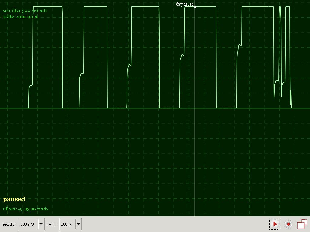
Heavy duty induction motor start-up current. The metering equipment max was at 672 A. 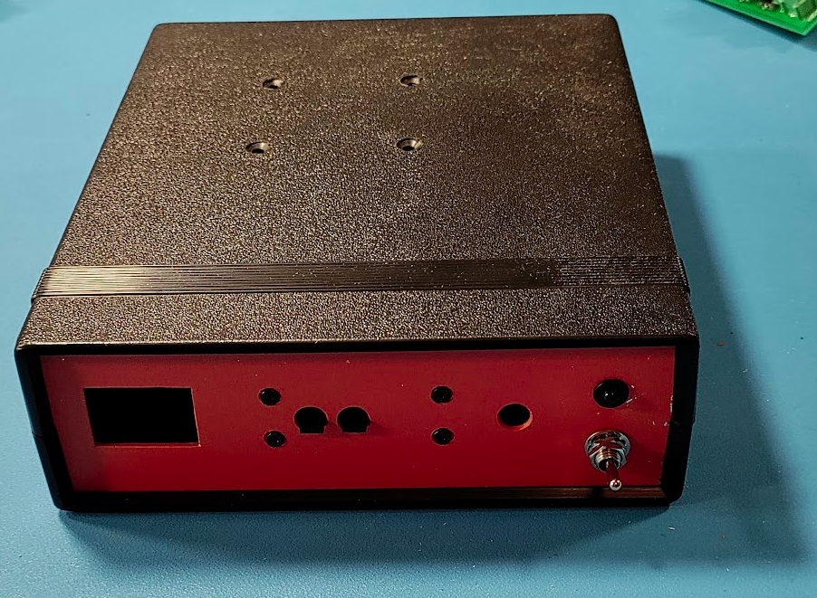
Micro amp current meter enclosure, yet to be finished 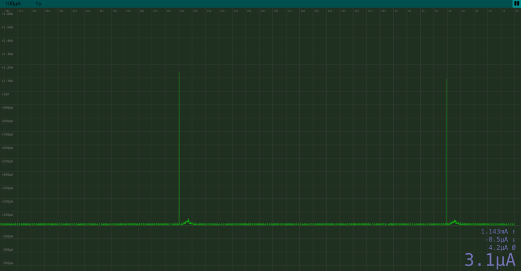
Measuring water flow meter current usage. Radio messages were set to be sent at 20 second intervals. Unfortunately this is the best picture available when writing this. Large spikes are radio messages being sent. Those very small constant spikes are not noise, they are caused by hall sensor measurements.
So, I ended up, again, building my own measuring device. It has a range of 0.5 µA to 67 mA. It is using a MCP356x 24-bit delta-sigma ADC, but in this case the actual accuracy is around 18-bits. It is connected to an Orange Pi which has a built-in web interface for using the measuring device. It also includes a built-in 0 to 4 V adjustable power supply, which makes it easier to test a device with different voltage levels. You could even simulate a battery. But that is enough about this, this goes off topic.
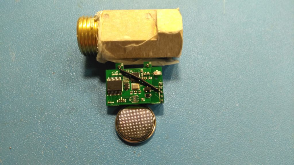
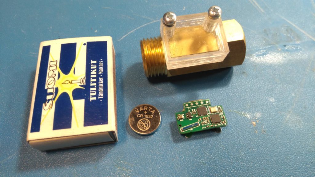
After the first prototype board came and I got into testing it, I actually got the current usage so low that CR1632 seemed a likely candidate as the battery. This also meant that I could get the PCB small enough to fit perfectly into an enclosure so small that it could be nicely mounted directly into the brass casing. CR1632 has a capacity around 120 mAh, according to wikipedia at least. So, at an average of 4 µA the battery would last roughly three years. Very good. And changing the send interval of radio packets to something like 10 minutes or even higher would lower the power consumption even more.
Then shortly about the overall tech.
First the water flow sensor itself counts pulses from the hall sensor and increases a counter accordingly. Then, at preset intervals, it sends that counter value out using a nRF24L01+ radio. The counter and the value sent is a 64-bit unsigned integer containing millilitres flown through the sensor since last power up (battery change etc). Actual accuracy of the counted value is desilitres.
That radio packet sent previously is received by a radio connected to gateway device. This device can be ESP32, Raspberry Pi, PC or something else able to use SPI bus to read data from nRF24L01+. This gateway also has to be able to forward received packets to LAN using broadcast. So, ethernet or WiFi connection is required. After that there is a simple python application that receives those broadcast messages, decrypts them and does other things required to authenticate the sender and to extract values from the packet that can be sent forward. If everything went ok, the data extracted from the packet can be now sent to MQTT broker and the rest is history.
Quite a lot of interesting technical stuff was left out, like RC5 encryption for radio packets and keeping PIC16LFx power consumption low etc, tried to keep it short. That’s about it for now.
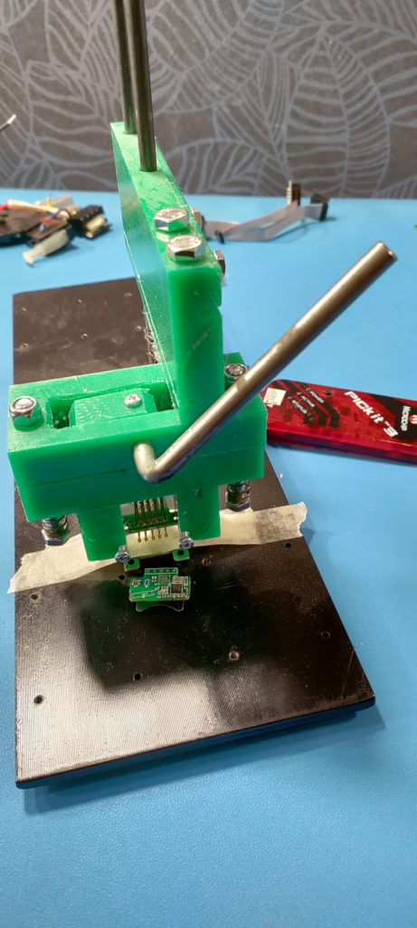
Oh, forgot this one, got frustrated programming those second version prototypes so I built this prototype of a generic adjustable programming platform with pogo pins:
