Building a simple VGA-adapter for 8-bit self made computer
(Update 2014-10-30: Due to some interest in this project, I added schematics for the GALs)
How to build your own VGA-adapter
My lifetime project: building an 8-bit computer using Z80 CPU. This week I had a bad flu and could not do anything useful so I decided to dig up my old plans for this project. I first re-designed many things, like power, CPU-board, IO-board and so on (my old plans were around 10 to 15 years old). After some thought I realized: When I get even the CPU-board working, I want to display some stuff! So why not build the display adapter first. Plus I planned to build the adapter in a way that it can be used separately from the computer itself. Easy thing to start with.
VGA as a standard was quite obvious choice. Composite-connection is getting quite old and there ain’t especially many monitors (or none?) supporting it anymore. VGA is old too, but it will still be around many years. Though VGA is bit too recent to be used in an 8-bit old-school computer, I decided that it is a good trade off between old and something still around. And I also decided to cheat a little bit on this part of my totally old-school computer.
Next thing was to find out about signalling. There are many resolutions and frequencies that can be used. After a lot of thought, 640 * 480 @ 60 Hz seemed the best as it is kind of a industry standard and uses the lowest pixel clock frequency, 25.175 MHz, supported by standard VGA resolutions. After looking around and thinking of ways to implement the adapter, I dug up some old GAL re-programmable logic IC’s which I got from an old Cisco(?) router/switch/whatever it was and some that I had bought from ebay. They seemed a very nice solution for this project because of their speed and flexibility, plus they are old going back to mid 1980 (they are based on PAL’s which are from late 1970).
Then came probably the biggest problem: Memory amount needed to display picture with 640*480 resolution. Monochrome picture would take 38400 bytes and 16 color (4-bit) image would take 153600 bytes. The monochrome picture would be ok, but the memory required for a 16 colors was just too much. I still wanted to be able to display 16 colors, but not with that amount of memory. I had some 128 kB SRAM’s lying around which was about the maximum I wanted this thing to have. Even that 128 kB is almost too much for a thing that is supposed to be old-school. But still, 16 colors would be nice.. So, thinking and thinking some more. Ping! I realized, I don’t have to draw all the pixel data from the memory. After some calculations I ended up with 512 * 384 resolution. Both numbers are nice round numbers in base-2 space. This leaves 128 horizontal pixels and 96 vertical lines empty, which means 64 pixels on right and left and 48 lines on top and bottom. Remember that quite large border in old computer screens on which there was no graphics? Heh, some accidents are nice. 512 * 384 resolution needs 98304 bytes when using 16 colors per pixel which fits nicely into 128 kB (24576 bytes for monochrome). I was kinda hoping to use 64 kB or less memory in this adapter but sometimes compromises are required.
Well, now for part 1: Creating the right signals for a VGA-display.
Part 1 – VGA-output signals
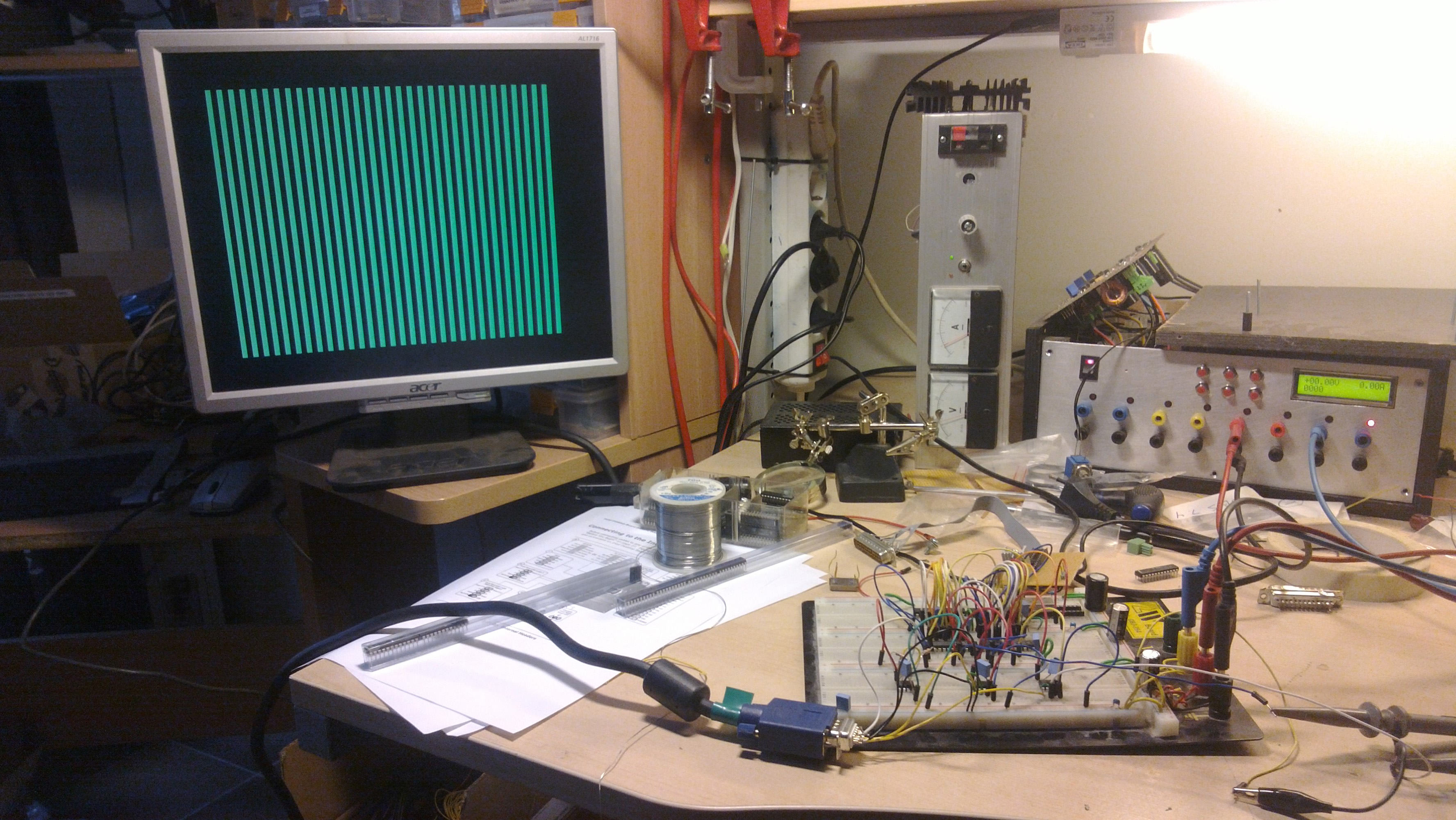
After getting the synchronization signals right, this was the first kind-of-image I got on the screen:
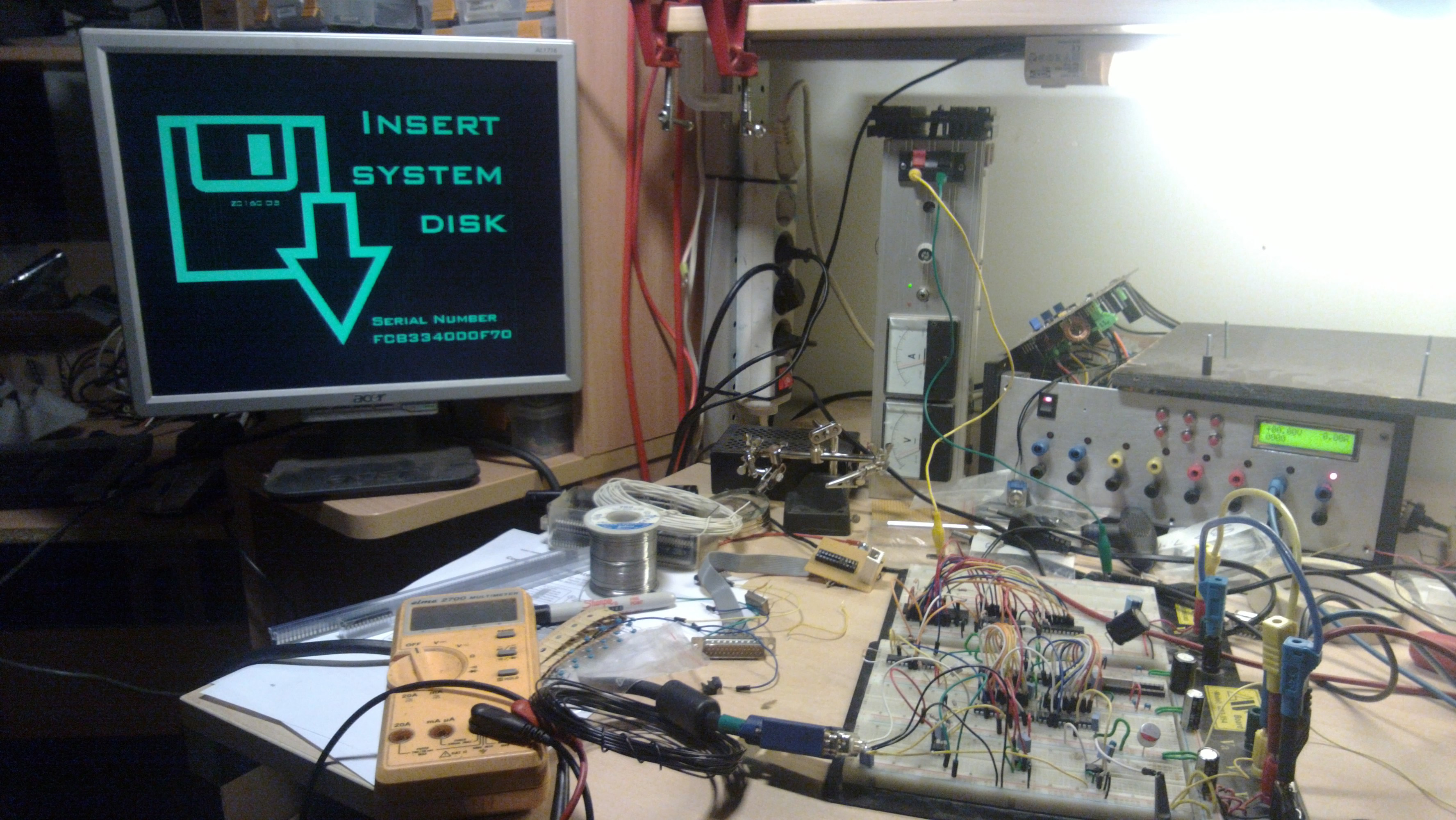
This was the first actual monochrome image displayed:
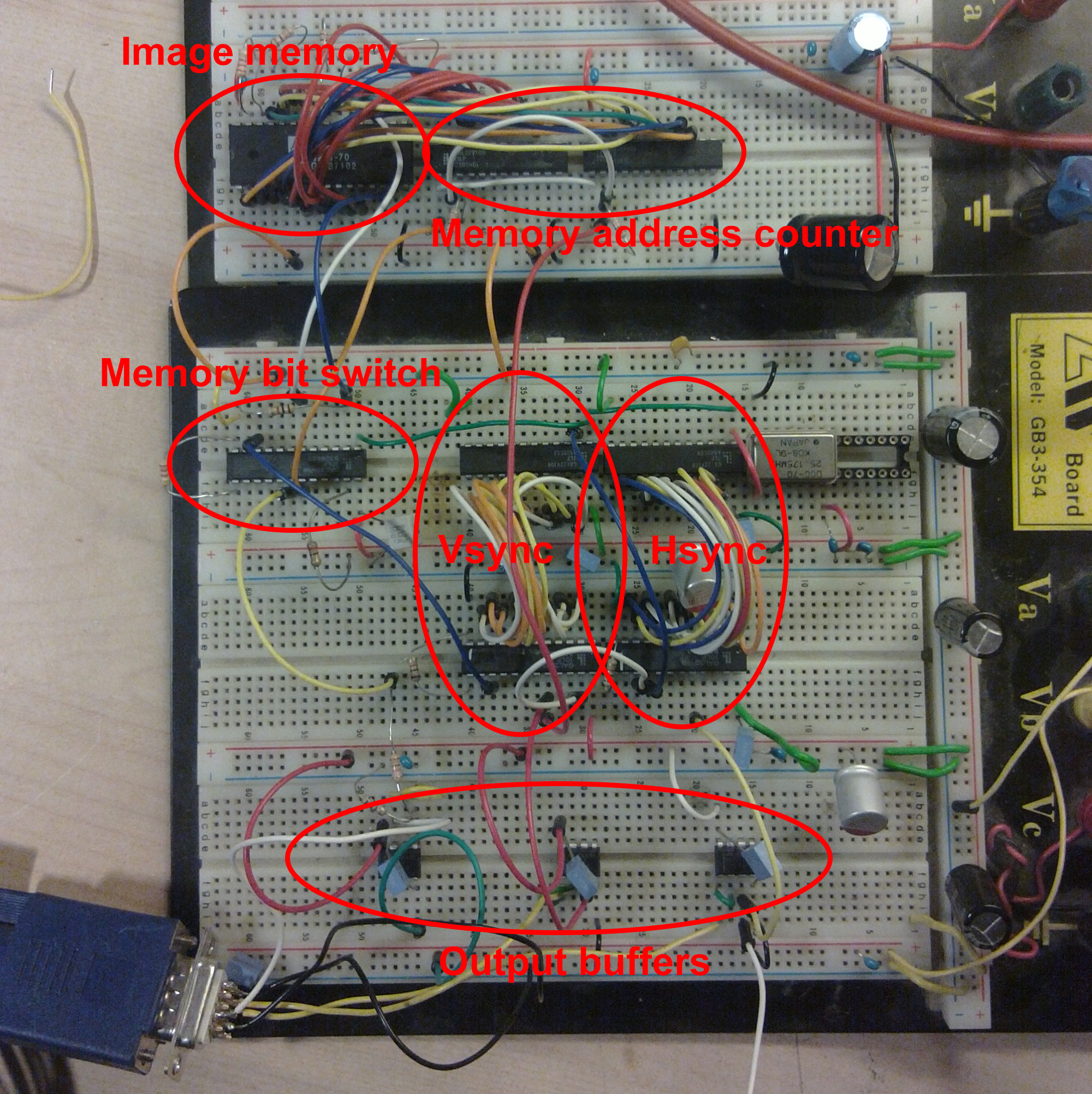
The breadboard was really easy to use for testing a thing running at 25.175MHz (the schematics later is different what is shown here):
Finalized schematic of hsync, vsync and color generation circuit (no memory or anything else like that included, just outputting of the signals plus kind-of-ramdac). Unfortunately this image does not tell much, since I used GAL16V8, GAL20V8 and GAL22V10 programmable logic circuits for this project. Building this thing with only discrete logic would have been a fun but too big project.

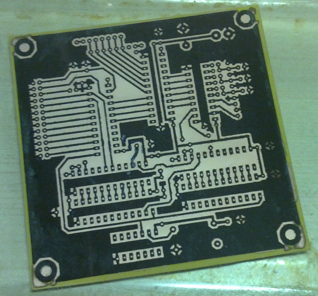
Waiting for the PCB to etch:
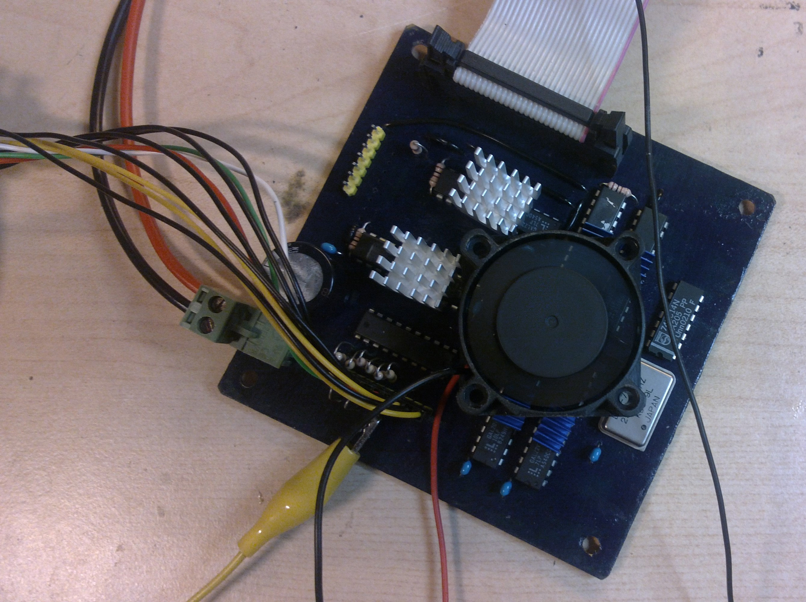
VGA-output circuit assembled and running:
I ran into something that got me laughing a lot when testing this hardware. I noticed that after few minutes image on the display started jiggling around. I got frustrated thinking that the problem was in the logic I had programmed into the chips or in the circuit itself. It had done the same in the breadboard and I hoped I would get rid of this problem when the device was assembled in PCB. Well, doing this, thinking that and with a blank stare at my face, I put my hand on the IC’s. They seemed quite hot and after few seconds picture on the display stopped jiggling. No.. No way.. Well, can’t hurt to test. I put few small PC graphics display card memory heat sinks onto the IC’s and would you believe it? The picture stopped jiggling and didn’t start again until after several minutes. I added small fan on top of the heat sinks and even after tens of minutes there were no problems. I laughed, my 16 color, 512 * 384 resolution simple VGA-card needed COOLING! Have to remember that next time when using those GAL-devices in high frequencies. They should be able to handle even higher frequencies without problems according to their datasheets. Side note: this circuit contains 6 GAL’s and not much anything else that would draw current. The whole thing draws around 0.6 A at 5 V, that is 3 W. This is only the output portion of the display card. And only one card in the whole computer. I’m gonna really need that big 10 A at 5 V power unit I was designing mostly just for the heck of it.
Schematics for GALs
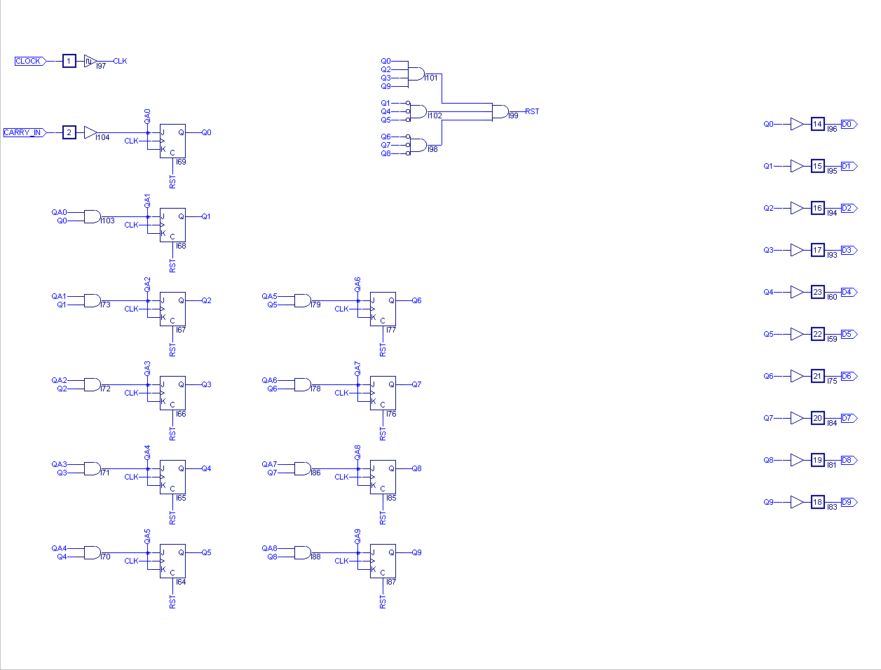
Counter for horizontal sync (U1)
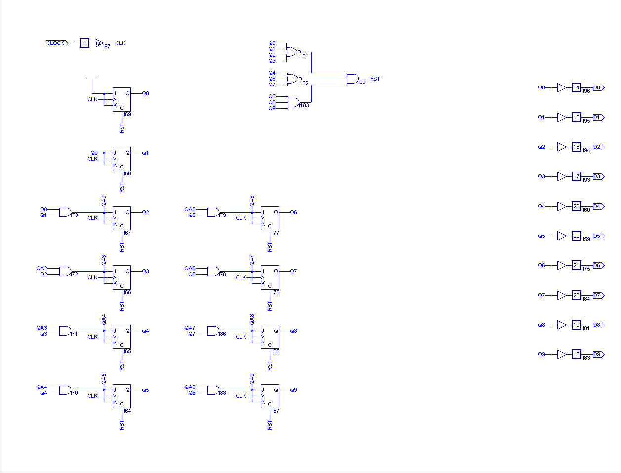
Counter for vertical sync (U2)
Horizontal sync generation (U3)
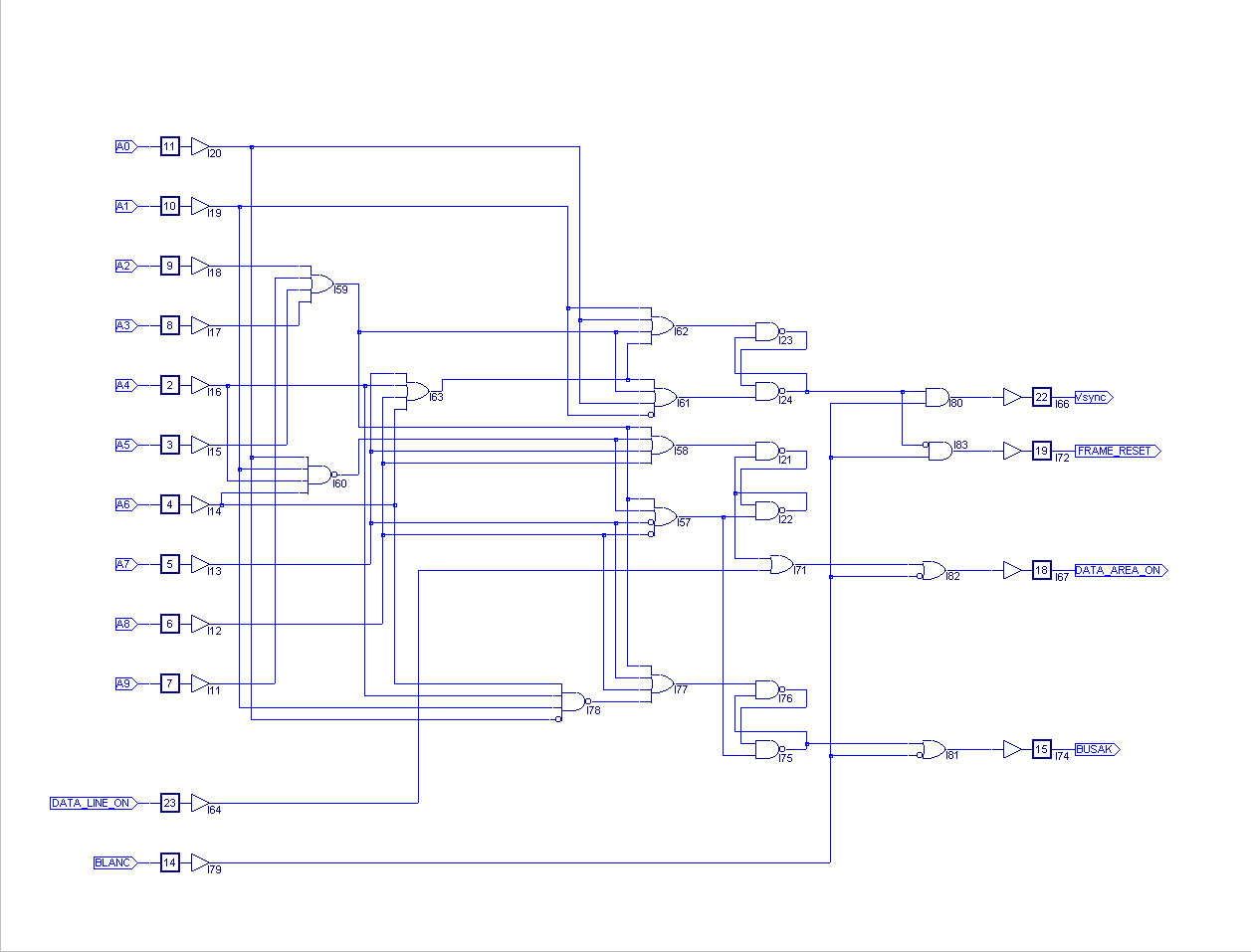
Vertical sync generation (U4)

Memory data to pixel data decoder (U6)
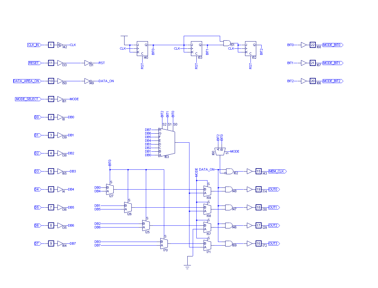
Color coder i.e. “RAMDAC” (U9)

Nice work! 🙂
Instead of a Z80 I used an 8051 (more exactly an 80C535) for my 8bit computer.
And instead of VGA, I used a LCDs with 320×240 pixels and a 4bit data interface (plus some control lines).
Furthermore, I used first a CPLD (Altera Max) and later a microcontroller (dsPIC30F4011) to continuously read the video data and display it (i.e. generate the control signals).
May I ask how you coordinate/synchronise the memory accesses of the RAMDAC (read only and display) and of the CPU (read/write), which generates the contents to be displayed?
Cheers,
Peter.
Well, rest of the display adapter is a work in progress (almost finished though)… I intend to put a separate Z80 on the display card itself as kinda ‘gpu’. During the blank period (front/back porch and sync) of the frame the cpu on the display card can access the display ram. During display draw the z80 bus request is called to put the display card cpu into hibernation so that the memory can be accessed freely by display refresh logic. At this point separate 8kB of the display card memory is accessible to the main z80 cpu and it’s nmi is called to alert about this. Then the main cpu will fill the 8kB with what ever it wants the display card cpu to do when it wakes up on the next blank period. When the blank period comes, this 8kB is linked back to the display card cpu address space. Shortly put, that’s it.
This will be quite complicated, but still possible to do with the hardware and chips that were available at the time when z80 was one of the top cpus 😉 That is one of my primary goals when building this machine, no parts that were not available back in the ’80s.
Thanks for the explaination! I like the approach. 🙂
I wish you all the best with your project!
Cheers,
Peter.
Thanks for the interest in this project, too bad I didn’t find anything on your project 🙂 Maybe you should write something to share the stuff you have made. For me this blog started really as a place to store my own thoughts for later and only for myself but search engines seem to find everything on the web 😛 Had to even upgrade the server a bit when somebody went and posted this on hackaday which created a load that my server could not handle 😀
Sorry for not answering earlier – boy! Time is flying… >.<
In the meantime I've tried some other approach to generating some "oldschool" video output.
Sadly, I only get around to tinkering in the night hours after my daytime job, which means slooooow progress.
Anyway, here are the first two samples:
https://www.youtube.com/watch?v=s6ywxzz7gBw
https://www.youtube.com/watch?v=9WaRH0K9McA
And yes, I'll also put some more info up on the web – soon… 😉
Cheers,
Peter.
Same problem, I do these things as a hobby when I have time after work. Now, on vacation, I got rest of the VGA-adapter designed. I just need to go through the design and order the PCB. But it might take few months 🙂 Let me know when you get some info on the web, nice videos so far.
Thanks so much for this project. I am trying to make a home-brew computer, complete with graphics too.
I am however confused and have a number of questions.
1. What do CR0, CR1, CG0, CG1, CB0, CB1 do? Are they necessary?
2. What does CONN-SIL-7 and CONN-SIL-10 connect to?
3. What does MODE_SELECT do? What does it have to do with pins 22, 21, 20 of U6 in the circuit diagram? I have compiled your circuits into a single mega-schematic and I can not figure out what to do about the mode-related lines.
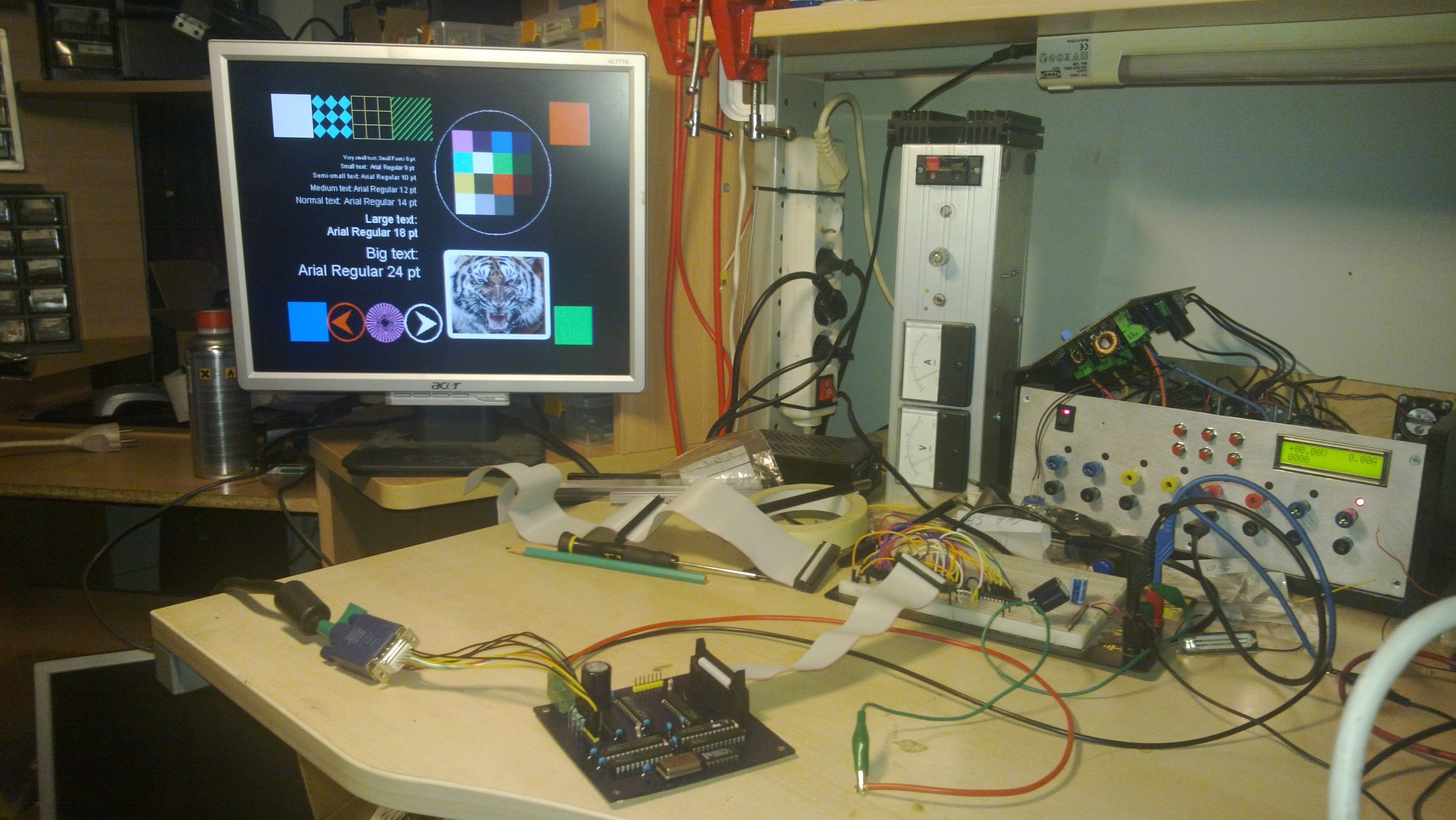
4. What testing setup did you use?
I don’t want to sound critical (I am definitly not), but I am genuinely confused, and really want to use this design in my computer.
Any help would be great.
Thanks!
Thanks for the interest in my project 🙂
1. They are for a custom color in 16 color mode and foreground color in 2 color mode. It makes 2 bits for each red, green and blue. I have a 74HC573 latch on the other side for these. The latch also holds BLANK and MODE_SELECT.
2. CONN-SIL-7 is the input for custom color plus blanking the screen (misspelled in the schematic). CONN-SIL-10 is the VGA-output connector, it can drive VGA monitors directly.
3. MODE_SELECT when low, selects 2 color mode. MODE_SELECT when high, selects 16 color mode.
4. Breadboard and a directly connected old 512 kiB flash memory from some PC motherboard. There was also a 17 bit counter for the address generation for the flash memory since this is the output portion only and accepts 8-bit input only.
The main idea is to use some external address counter (I build one from two GAL22V10) with MEM_CLOCK, FRAME_RESET and DATA_AREA_ON. MEM_CLOCK is the clock for the external address counter, FRAME_RESET tells the counter to reset itself and DATA_AREA_ON enables the counter. When DATA_AREA_ON is not active (is high), the counter should not count.
I have not found too many VGA output devices sources for the Z80 Cpu. I have the RC2014 but the video card offered is only text based with a ri pi zero. Will the board be available on OSH park? I have a hard time viewing the schematic.
Hi, I don’t see any reason why I could not share this board. But its quite big and OSH park gets expensive with larger boards. So I ordered this board from allpcb.com. Paid something around 40-50€ there. OSH park would cost 2-3 times that for board like this.
Also it is not the simplest to assemble. You need the GAL’s and you need to program them. For that TL866 universal programmer is a good choice, BUT: it has problem programming GAL22V10 chips. I had to program GAL22V10 chips the old fashioned way: Windows 98, galblast and a parallel port.
Maybe I shall have more time in the future to write an extensive report on this adapter 🙂
That is interesting, I have a TL866 programmer. I also have a windows 95 laptop floating around but have never worked with galblast. I guess the question comes down to how difficult it is to program. Uploading the CP/M rom that Grant had for the Z80 was fairly straight forward.
Nice work
Thanks so much for sharing this project. I am trying to make a Z80 based home-brew computer, complete with graphics too. But I cant easily find those gal/pal ic’s .. can I do the whole thing with standard ttl ic’s ? I found that max speed of 7400 ttl logic series is about 25mhz .. but as you have on your schematics the needed frequency for the pixel frequency is 25.175mhz ..Its a lot nicer to have a vga output rather than messing around with composite video but with vga timings are getting higher as the resolution goes up …
Thanks in advance! Nice work !
Well, of course it is possible to do this using standard TTL chips. Just harder. 74HC-series is faster but it is also newer so kinda cheating when building old school computer 🙂 I was originally hoping to use only standard TTL chips, but just the size of the PCB would be huge and this display adapter is only one part of the whole computer.
Hi,
Would you mind sharing the .PLD files for Hsync and/or Vsync signal generation ? I’m new to GAL programming and I have a very hard time to translate your schematics into equations. There must be something that’s escaping me, and your help would be much appreciated.
Thanks in advance!
Hi, unfortunately I have only shared the schematic files for Lattice ispLEVER Classic in my github.
What software did you use to draw schematics for the PLDs? I have used WinCUPL. But have never seen the software you are using.
Also, as mentioned in the earlier comments, the TL866 is hit or miss when programming the 22V10. I have found that the ELM Programmer is still reliable assuming you have a DOS machine to run it on.
I used Lattice ispLEVER Classic. I have been using self-made printer port programmer with a software called galblast, which works fine using VirtualBox with Windows 98 and printer port passthrough.
How does it communicate with Z80 used as the CPU? Which pins are used? Is there some assembly code needed?
All the code for this project is written in assembly. This “GPU” communicates with the CPU through 2 KB dual port RAM. Though the part of this project described in this post was only about generating the required signals for VGA.
“But I cant easily find those gal/pal ic’s” — I found that GALs are quite cheap at aliexpress.com, so may be a good approach (although if you don’t have a programmer those can be a bit expensive).
“I found that max speed of 7400 ttl logic series is about 25mhz” Using 74Sxxx and 74Fxxx parts ought to be able to cope with the speed required quite easily. Most of the logic would be perfectly fine even with 74LSxxx devices, but counters could be a bit tricky — e.g. the 74LS293 counter can count at 32MHz, but is only 4 bits wide… to extend it out to the 10 bits required for the hsync counter here will slow it down because you’ll need 3 of them in a chain, and waiting for all 3 to settle after a clock pulse will typically require 3*34 + 10 = 112ns, so about 9MHz is the most you could hope for. The 74F269 however would work: to start with it’s 8 bits wide, so you’d only need two of them, and has a 9-10ns response time, so you could have two of them running together at 50MHz if you wanted.
Much more problematic is that over about 10-15MHz you start to have to worry a lot more about your PCB design (e.g. having traces that are roughly equal length for signals that need to arrive at the same time), which is of course harder the more complex your circuit gets. GALs therefore look *very* tempting to me too. 🙂
Was just wondering if you considered using an off-the-shelf display timing chip (e.g. MC6845 or similar) to generate your sync pulses and pixel/row counters, and if so why you decided on GALs for this? I think you could have reduced your chip count by 3 by using a 6845, and they’re readily available on ebay/aliexpress/etc.
I did, but it seemed “too easy”. Generating all the signals with generic logic was more interesting. Next hard part will be implementing 10BASE-T ethernet adapter with the same kind of logic. I have done the basic is-this-even-possible-research. Can be done, someday..
Hello! Nice project… I wish to replicate. Could you publish your jed files to program the GAL’s?
I have done the designs using ispLEVER Classic Software. Everything can be found here (but .jed files, since I do not like to put automatically generated stuff in version control): https://github.com/aehparta/zc160
Possibly your ‘jiggling’ problem could be due to floating inputs on either PAL/GALS or other logic – I have cured similar design flaws in such a way. – I recommend tying all unused GAL/PAL input pins to ground 🙂
I ordered a factory-built PCB for the card and haven’t had problems anymore 🙂